4.04 - Structured Analysis & Design Technique (SADT)
Introduction
A number of techniques have been devised to assist with re-engineering business processes. They include Work Study, Systems Analysis, Computer Analysis, Data Flow Diagramming, Soft Systems Analysis and other methods such as the Unified Modelling Language (UML). All of these have their place. However, the "boxology" (the symbols and signs employed) force a number of preconceptions on the way things are done. The SADT (IDEF0) technique is free of these initial preconceptions and can be used to model any system without constraining the way the system is eventually embodied – by paper procedures, using people or by using machines (usually computers).
Definition and Background
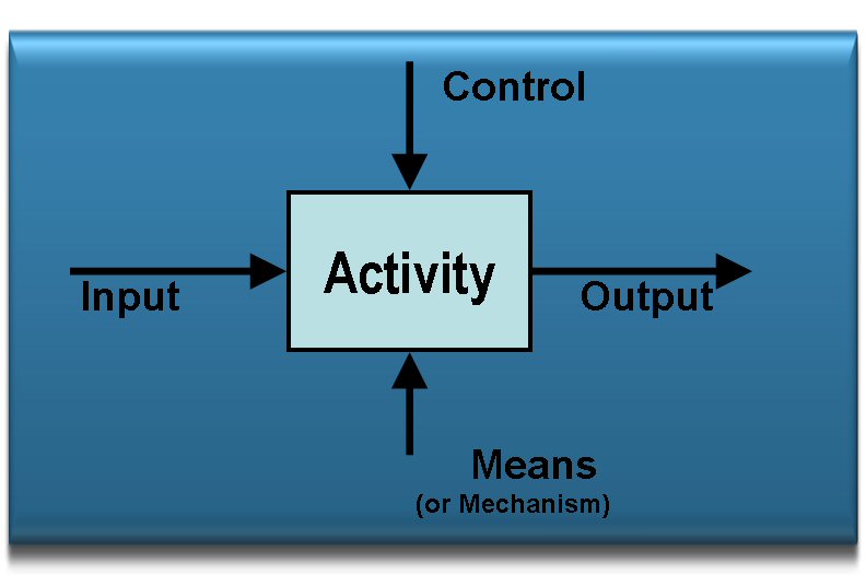
The Structured Analysis & Design Technique (SADT) is a process modelling technique developed by D T Ross of SofTech Inc. Later a subset of the technique was adopted by the US Air Force ICAM project, renamed IDEF0 and placed in the public domain. The technique is used to analyse complex systems by breaking them down in a structured fashion to arrive at the constituent parts of the system under consideration. It is a graphical description language specifically designed to assist understanding of business processes. The basic module of the technique is a process box denoting an activity. It shows inputs coming in from the left and outputs going out from the right. Controls for the activity are shown at the top and the means of transforming the inputs into outputs are shown at the bottom thus:

Fig 1. The IDEF0 (SADT) process box
Activity |
Anything that can be named with an active verb phase (e.g. produce drawing) and is a process element |
Input Data |
Data needed to perform the activity. A system specification or customer requirements for instance. |
Control |
Describes the conditions or rules that govern the way the activity is performed. For instance; business procedures, calculation rules, check lists,
measures of performance etc. |
Output Data |
Data or things created when the activity is performed. For example parts, data or documentation |
Means |
The way the activity is undertaken. For example, a specific job role, a machine, device and/or a software application such as CAD or a Word Processor.
It could aslo be a specific technique such as DFA or QFD stage. |
Business Benefits
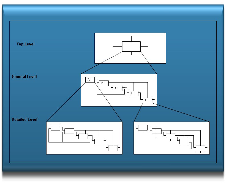
The structured techniques show what is being done by an activity, the controls show why it is done and the mechanism shows how it is done. The general approach is to start with a global view of a subject, or system, and then break this down to progressively more and more levels of detail. In this way we avoid trying to deal with to much detail all at once and it leads to more thorough analysis of a subject. Once analysed the individual processes are arranged in a hierarchical structure to show their relationships to each other so the main flows can be identified. The hierarchical relationships are shown below:

Fig 2. The SADT (IDEF0) Model Structure
Process Modelling in the Product Life-cycle Management Context
Product Life-Cycle management (PLM) systems are designed to control and manage product data and the processes that create or use that data. In the past this has been managed by paper and people procedures. These control systems are generally very inefficient and error prone. To apply PLM effectively we must re-engineer the processes to take full advantage of PLM work flow capabilities. This is usually accomplished by making a number of models of a system or business process. They are models of:
- the existing system
- the ideal system, and
- the achievable system.
In other words, the technique allows the following to be modelled:
- the system "AS-IS,"
- the system as it should be, fulfilling its functional requirements without taking constraints of any kind into account, and
- the system "TO-BE" produced, taking into account, not only, the functional requirements, but also various constraints such as: cost, reliability, etc.
Process modelling is an important aspect of PLM implementation and should not be skimped or overlooked as it has an impact on the success of the PLM project. However, "to-be" modelling must take into account PLM system capability so an early appraisal of PLM technology needs to take place before undertaking process re-design. This approach can be supported by parallel activities of process analysis and PLM capability evaluation. Additionally, the achievable system is not going to be produced in one shot. Logically, therefore, there will be a number of "to-be" models reflecting the various phases of PLM implementation as the company continuously improves its product development processes.
Notes:
In part SADT, or IDEF0, is similar to the BOSCARDE method of defining a Terms of Reference (TOR) or a Statement of Work (SOW) for a work package in a project (see Guide 2.07). It is still used as a briefing framework by effective managers when allocating work to their team members. BOSCARDE is an acronym for:-
- Background
- Objectives
- Scope
- Constraints
- Assumptions
- Reporting
- Deliverables
- Estimates
Additionally the SADT or IDEF0 process modelling technique does not cover the exit conditions from each of the processes described. That can be covered in the text or by the use of other “boxologies”. For instance CORE (see guide 4.05) extends the description of the Control mechanism.
A comparison of UML and the IDEF family of techniques is made by a number of workers in the field and is widely accessible on the internet.
One such paper is “Business Modelling: UML vs IDEF” (2000) by Ovidiu S Noran.
“There is no such thing as a final solution or a universal tool. The challenge is not to find the ultimate tool, but the right tool for the job. The same applies to business modelling.”