6.16 - Process Selection
Selecting the right process and optimising the design to that process involves a series of design decisions that have a direct impact on product quality and cost. These decisions, in turn, affect the market viability of the end product to which the components belong.
A manufacturing process selection strategy is shown below:-
- Obtain an estimate on the annual production quantities required
- Choose a material type that satisfies the PDS
- Select a range of possible candidate processes
- Validate each possible process against technical and cost factors thus:-
- Understand the broad process group and its variations
- Consider material / process compatibility
- Assess conformance of the component design concepts with design rules
- Compare tolerance and surface finish requirements with the process capabilities
- Consider the targeted process cost and obtain estimates for alternative processing methods
- Review the selected manufacturing process against the business requirements
Many researchers have prepared process descriptions and parameters and cross-referenced them against the materials available. This is the subject of intense research so that more rapid cost estimates can be obtained along with the process selection. Some software products are available that directly produce list of candidate processes as a direct result of analysing the geometric shape in the CAD model. These software products are being developed using content from CAPP or CAPPES software products as the basis. Some have been developed from DFMA / DFA software and some are being developed by the CAD software vendors.
In any case they use a means to cross reference the materials to the process similar to the next table.
The numbers in the matrix indicate the maximum annual volume expressed as 10X where X is from the matrix.
Materials è
ê Processes |
Ferrous |
Non-ferrous Alloys |
Non-Metals |
|
|
| |
|
|
|
|
|
|
|
|
|
|
|
|
|
|
|
1.01 – Sand Casting |
7 |
7 |
3 |
7 |
7 |
7 |
7 |
3 |
3 |
3 |
7 |
3 |
|
|
|
|
2 |
|
1.02 – Shell Moulding |
6 |
4 |
4 |
4 |
6 |
6 |
|
|
|
|
4 |
|
|
|
|
|
|
|
1.03 – Gravity Die Casting |
6 |
4 |
|
|
4 |
6 |
6 |
5 |
5 |
5 |
4 |
|
|
|
|
|
|
|
1.04 – Pressure Die Casting |
|
|
|
|
5 |
6 |
6 |
6 |
6 |
6 |
|
|
|
|
|
|
|
|
1.05 – Centrifugal Casting |
4 |
4 |
4 |
4 |
4 |
4 |
|
|
|
|
4 |
|
|
|
|
2 |
|
|
1.06 – Investment Casting |
4 |
7 |
7 |
7 |
7 |
7 |
4 |
|
|
|
7 |
3 |
|
|
|
|
7 |
7 |
1.07 – Ceramic Mould Casting |
4 |
4 |
4 |
4 |
3 |
3 |
3 |
3 |
3 |
|
4 |
|
|
|
|
|
|
|
1.08 – Plaster Mould Casting |
|
|
|
|
4 |
4 |
4 |
4 |
4 |
4 |
|
|
|
|
|
|
|
|
1.09 – Squeeze Casting |
|
6 |
|
6 |
6 |
6 |
|
|
|
|
|
|
|
|
|
|
|
|
2.01 – Injection Moulding |
|
|
|
|
|
|
|
|
|
|
|
|
6 |
6 |
5 |
|
|
|
2.02 – Reaction Injection |
|
|
|
|
|
|
|
|
|
|
|
|
|
4 |
4 |
|
|
|
2.03 – Compression Moulding |
|
|
|
|
|
|
|
|
|
|
|
|
5 |
6 |
5 |
|
|
|
2.04 – Transfer Moulding |
|
|
|
|
|
|
|
|
|
|
|
|
|
6 |
|
|
|
|
2.05 – Vacuum Forming |
|
|
|
|
|
|
|
|
|
|
|
|
5 |
2 |
|
|
|
|
2.06 – Blow Moulding |
|
|
|
|
|
|
|
|
|
|
|
|
6 |
|
|
|
|
|
2.07 – Rotational Moulding |
|
|
|
|
|
|
|
|
|
|
|
|
4 |
|
|
|
|
|
2.08 – Contact Moulding |
|
|
|
|
|
|
|
|
|
|
|
|
|
|
3 |
|
|
|
2.09 – Continuous Extrusion |
|
|
|
|
|
|
|
|
|
|
|
|
6 |
6 |
|
|
|
|
3.01 – Closed Die Forging |
|
6 |
5 |
5 |
6 |
6 |
6 |
|
|
|
5 |
5 |
|
|
|
|
|
|
3.02 – Rolling |
|
6 |
|
6 |
6 |
6 |
|
6 |
|
6 |
6 |
|
|
|
|
|
|
|
3.03 – Drawing |
|
6 |
|
6 |
6 |
6 |
6 |
6 |
6 |
6 |
6 |
|
|
|
|
|
|
|
3.04 – Cold Forming |
|
6 |
5 |
5 |
6 |
6 |
6 |
6 |
6 |
6 |
5 |
5 |
|
|
|
|
|
|
3.05 – Cold Heading |
|
6 |
5 |
5 |
6 |
6 |
5 |
6 |
|
5 |
5 |
|
|
|
|
|
|
6 |
3.06 – Swaging |
|
7 |
7 |
7 |
7 |
7 |
7 |
7 |
|
7 |
7 |
|
|
|
|
|
|
|
3.07 – Super-plastic Forming |
|
|
|
4 |
6 |
4 |
|
|
|
|
|
4 |
|
|
|
6 |
|
|
3.08 – Sheet Metal Shearing |
|
7 |
|
7 |
7 |
7 |
7 |
7 |
|
|
7 |
7 |
|
|
|
|
|
|
3.09 – Sheet Metal Forming |
|
7 |
|
7 |
7 |
7 |
7 |
7 |
|
|
7 |
7 |
|
|
|
|
|
|
3.10 – Spinning |
|
4 |
2 |
4 |
4 |
4 |
4 |
4 |
4 |
4 |
4 |
4 |
|
|
|
|
|
|
3.11 – Power Metallurgy |
6 |
5 |
5 |
5 |
6 |
5 |
|
|
|
|
5 |
5 |
|
|
|
6 |
|
|
3.12 – Continuous Extrusion |
|
6 |
5 |
5 |
6 |
6 |
6 |
5 |
5 |
5 |
5 |
5 |
|
|
|
|
5 |
|
4M – Machining – Manual |
3 |
3 |
3 |
3 |
3 |
3 |
3 |
3 |
3 |
3 |
3 |
3 |
|
|
|
|
|
|
4A – Machining – Automatic |
6 |
6 |
6 |
6 |
6 |
6 |
6 |
6 |
6 |
6 |
6 |
6 |
|
|
|
|
|
|
5.01 – EDM |
|
3 |
3 |
3 |
3 |
|
2 |
|
|
|
3 |
3 |
|
|
|
3 |
|
|
5.02 – ECM |
4 |
5 |
5 |
4 |
4 |
|
|
|
|
|
5 |
5 |
|
|
|
4 |
|
|
5.03 – EBM |
3 |
4 |
4 |
4 |
4 |
4 |
|
|
|
|
4 |
4 |
|
|
|
4 |
|
|
5.04 – Laser Beam Machining |
3 |
4 |
4 |
4 |
4 |
4 |
|
|
|
|
4 |
4 |
|
|
|
4 |
|
|
5.05 – Chemical Machining |
|
5 |
4 |
4 |
7 |
5 |
4 |
4 |
3 |
3 |
5 |
5 |
|
|
|
7 |
|
4 |
5.06 – Ultrasonic Machining |
|
2 |
3 |
2 |
|
|
|
|
|
|
2 |
3 |
|
|
|
3 |
|
|
5.07 – Abrasive Jet Machining |
|
|
3 |
|
|
|
|
|
|
|
|
3 |
|
|
3 |
3 |
3 |
|
Chart adapted from “Process Selection: From Design to Manufacture” by Swift & Booker |
The previous chart is by no means exhaustive – it serves to illustrate what the main factors are. There are many sub-factors to selecting a process to match a material selection. Some are shown below:-
- Cost of manufacture
- Geometric Shape
- Actual Material Specification
- Tolerances / Surface Finish
- Tooling, Jigs and Fixtures
- Gauges
- Available Equipment (in-house or in the Supply Chain)
- Delivery Date
Process Selection in a Strategic Context
As the design team considers materials and processing alternatives as possible solutions to design problems they need access to the kind of information shown in the previous table. The example table in this guide could serve as a starting point. It is biased towards the metals and metals processing. With the increase in the use of non-metals similar data collection and collation efforts should be made for that group of materials. The objective is to get a rapid turnaround on the relative costs of ALL candidate processes. This enables:-
- The generation of alternative and cost effective design ideas that facilitates the matching of available manufacturing processes to those ideas
- Using that data in the roll-up of component and assembly costs to measure design performance against Target Costs and Target Weights.
Some firm’s competitive advantage comes from the ability to “design” new materials and processes and do not want that expertise to become public. They may use a generic materials and process selection system or method and add their own data to the system to make that knowledge available within the company.
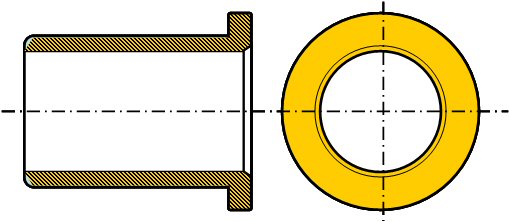
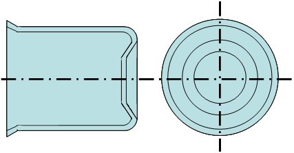
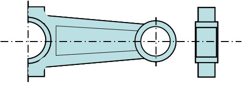
The output from computerised material and process selection systems can be presented as shown in the following diagrams to enable designers to make rapid trade-off decisions. The costs in this table are relative.
Component Design |
Mat’l |
Annual Qty |
Process |
Relative Merits |
Cost |

Plug Body |
Low Carbon Steel |
1,000,000 |
Machining |
High waste
Low-med prod rates
Poor strength |
3.9 |
Cold Forming |
Low waste
Very high prod rates
High strength |
1.0 |
Plain Bearing |
Bronze |
50,000 |
Machining |
High waste
Low-med prod rates
Non-Porous |
2.2 |
Powder Metal Sintering |
Low waste
High prod rates
Porous part |
1.0 |
Cover |
Alum Alloy |
5,000 |
Spinning |
High Labour Cost
Low Prod rates
Low detail/accuracy |
1.8 |
Deep Drawing |
Low Labour Costs
High prod rates
High detail/accuracy |
1.0 |
Con rod |
Med Carbon Steel |
100,000 |
Closed Die Forging |
Long lead times
High tooling & equipment costs |
1.3 |
Sand Casting |
Short lead times
Low tooling & equipment costs |
1.0 |
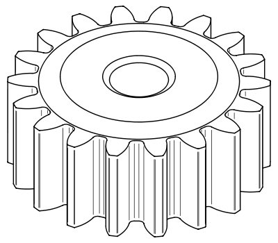
Spur Gear |
Low Carbon Steel |
5,000 |
Machining |
High waste
Low-med prod rates
Poor strength |
2.6 |
Cold Extrusion |
Low waste
Very high prod rates
High strength |
1.0 |
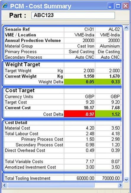
A supplementary display giving instant feedback to the CAD designer on the cost of design ideas as the design is iterated also speeds process selection (see diagram
below).
